Mitee-Bite ID Xpansion Clamp

Brand: Mitee-Bite CNC Fixture ClampsMitee-Bite CNC Fixture Clamps
CAD50.04 EA
Select
Cost: CAD50.04 EA -
Add to cart

ID Xpansion™ Clamps

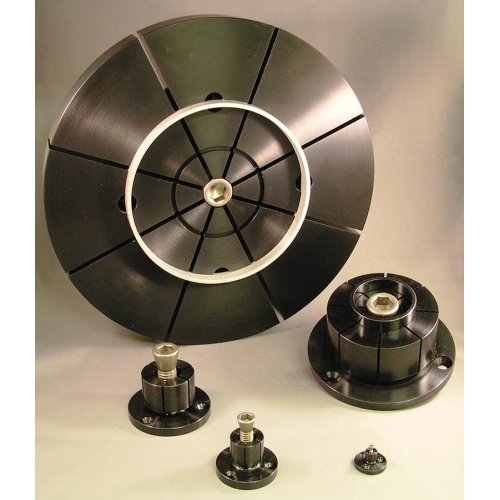
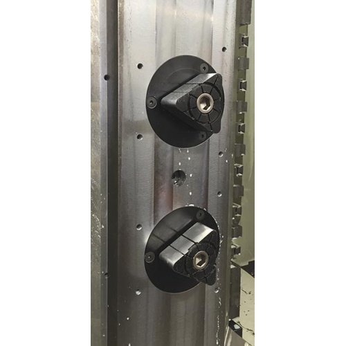
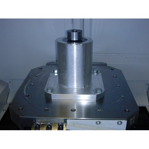
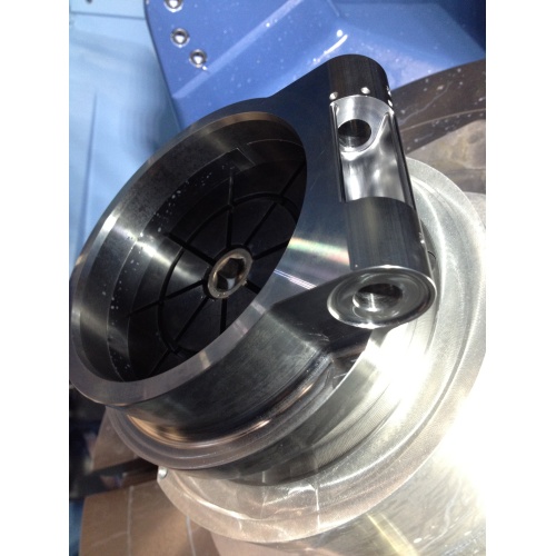
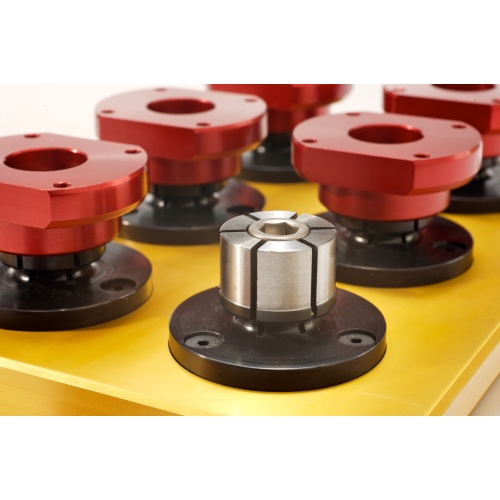
The ID Xpansion™ clamp is the ideal solution to hold parts on an inside diameter for high density machining on vertical or horizontal machining centers. It can also be used as an expanding mandrel on a lathe.

These machinable clamps are produced in 12L14 steel with black oxide coating in 12 sizes and can hold internal diameters from under 3/16 to almost 10 inches (4.1 to 254mm). #10 manufactured using 7075-T6 aluminum.

The flange diameter of the clamp is held to a close tolerance for precision locating in a machined pocket on work cubes and fixture plates.

The customer machines the mild steel clamp to match the bore of the part ensuring a proper fit. Often times the clamps can be remachined for different size jobs.

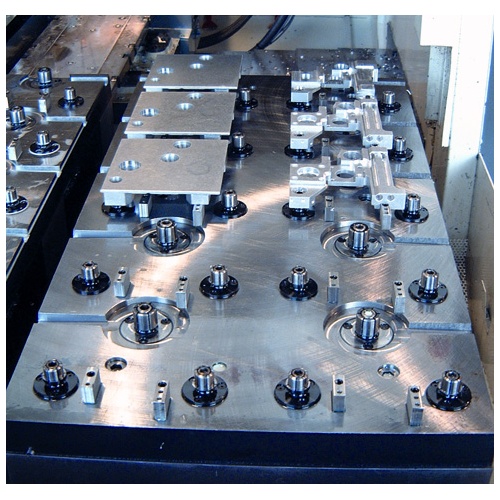
The low profile ID Xpansion™ Clamp can hold several parts in one compact area for secondary operations without any clamping interference. They are quickly tightened with a hex key, torque driver or can be mated to hydraulic pull cylinders for automation.

  • Low Profile
  • Ideal for Secondary Operations on lathe parts
  • Easily machined to size on lathe or mill
  • Excellent for palletized setups
  • Allows more parts per workcube or fixture plate
  • Heat-treated and coated screw for long life
  • Clamp body made of mild steel for machinability
  • Tighten with hex key or hydraulic pull cylinders
    (Drill clearance hole for longer bolt into cylinder)
  • Longer screws available for hydraulic applications
  • Longer tapered screws available for each ID size
ID Xpansion Clamp

Clamp Machining and Installation

Inch

Part
Number
Model
Number
 ABCDE+.000
-.002
FG+H*IJTorque
(Ft/lbs.)
Holding
Force (lbs)
Replacement
Tapered Screws
31000 #00   .42 .30 .24 .12 .787 .29 .16 2-56 on .540 BHC 2-56 x 1/4 .16 0.5 250 31001
31050 #0   .86 .63 .59 .23 1.170 .49 .28 6-32 on .825 BHC 8-32 x 1 .30 3.6 950 31002
31100 #1   .98 .75 .59 .23 1.240 .56 .48 6-32 on .910 BHC 1/4-20 x 1 1/4 .50 13.3 1,900 31010
31150 #2   .98 .75 .59 .23 1.476 .79 .53 6-32 on 1.140 BHC 5/16-18 x 1 1/4 .56 27.6 2,500 31020
31200 #3   1.13 .88 .69 .25 1.968 1.06 .71 8-32 on 1.550 BHC 3/8-16 x 1 1/2 .71 49.3 4,500 31032
31250 #4   1.25 1.0 .81 .25 2.205 1.39 .90 8-32 on 1.790 BHC 1/2-13 x 1 1/2 .71 120.0 5,900 31042
31300 #5   1.56 1.25 1.06 .31 2.736 1.65 1.15 10-32 on 2.200 BHC 5/8-11 x 1 3/4 .79 224.0 10,000 31052
31350 #6   1.56 1.25 1.06 .31 2.972 2.03 1.15 10-32 on 2.515 BHC 5/8-11 x 1 3/4 .79 224.0 10,000 31052
31400 #7   1.79 1.48 1.27 .31 4.232 3.06 1.15 1/4-20 on 3.646 BHC 5/8-11 x 2 .79 224.0 10,000 31072
31450 #8   1.79 1.48 1.27 .31 5.232 4.06 1.15 1/4-20 on 4.648 BHC 5/8-11 x 2 .79 224.0 10,000 31072
31500 #9   1.79 1.48 1.27 .31 5.232 6.89 1.15 1/4-20 on 4.648 BHC 5/8-11 x 2 .79 224.0 10,000 31072
31550** #10   1.79 1.48 1.27 .31 6.000 9.85 1.15 1/4-20 on 5.250 BHC 5/8-11 x 2 .79 125.0 6,000 31072
G+ Minimum diameter the “F” dimension can be machined or turned down to.
H* – (3) Mounting Screws Included. (4) Mounting Screws Included with #9 & #10.
** – Clamp made from 7075-T6 aluminum.

ID Xpansion™ Clamp Machining and Installation

MODEL #00 – #6 ID Xpansion™ Clamps
  • Expand clamp approximately .002 to .003 over relaxed diameter and machine to fit workpiece bore, either on lathe or mill.
  • If machining the clamp on a lathe use the nut provided, on the back of the clamp, to tighten the tapered screw. This nut is used only while machining the clamp.
  • Machine a pocket in the fixture, for the close tolerance “E” dimension and drill and tap mounting holes per “H” column. Drill and tap a hole from the “I” column in the center of the pocket for the tapered screw.
  • A recessed dowel pin may be installed into the flange for additional rigidity if required.
  • Custom screws available for blind hole applications.
  • Range of expansion .005 to .025 depending upon size.
MODEL #7-10 ID Xpansion™ Clamps
  • Locking ring provided to ensure segments remain rigid while machining clamps to size. #10 ID ships with 2 rings.
  • Insert ring(s) and tighten drive screw, machine clamp to bore size. Remove ring(s) to clamp workpiece.
  • Expand mandrel then machine to size.
  • Aggressive material removal is not recommended when machining clamps to size.

Metric

Part
Number
Model
Number
 ABCDE+.000
-.050
FG+H*IJTorque
(N.m.)
Holding
Force (N.)
Replacement
Tapered Screws
38000 #00   10.7 7.6 6.1 3.0 20.0 7.4 4.1 M2 on 13.7 BHC M2x12 4.1 .70 1,113 38001
38050 #0   21.8 16.0 15.0 5.9 29.72 12.4 7.1 M3 on 20.95 BHC M4x25 7.2 5.00 4,228 38002
38100 #1   24.9 19.0 15.0 5.9 31.5 14.2 12.2 M3 on 23.1 BHC M6x30 11.2 17.00 8,455 38010
38150 #2   24.9 19.0 15.0 5.9 37.5 20.0 13.5 M3 on 29.0 BHC M8x30 13.2 34.00 11,125 38020
38200 #3   28.6 22.2 17.5 6.4 50.0 27.0 18.0 M4 on 39.4 BHC M10x35 16.3 60.00 20,025 38032
38250 #4   31.8 25.4 20.6 6.4 56.0 35.3 23.0 M4 on 45.5 BHC M12x40 20.3 150.00 26,255 38042
38300 #5   39.6 31.8 27.0 7.9 69.5 42.0 29.3 M5 on 55.9 BHC M16x45 21.4 280.00 44,500 38052
38350 #6   39.6 31.8 27.0 7.9 75.5 51.5 29.3 M5 on 63.9 BHC M16x45 21.4 280.00 44,500 38052
38400 #7   45.5 37.6 32.3 7.9 107.5 77.7 29.3 M6 on 92.6 BHC M16x50 19.3 280.00 44,500 38072
38450 #8   45.5 37.6 32.3 7.9 132.9 103.0 29.3 M6 on 118.06 BHC M16x50 19.3 280.00 44,500 38072
38500 #9   45.5 37.6 32.3 7.9 132.9 175.0 29.3 M6 on 118.06 BHC M16x50 19.3 280.00 44,500 38072
38550** #10   45.5 37.6 32.3 7.9 152.4 250.2 29.3 M6 on 133.35 BHC M16x50 19.3 170.00 26,000 38072
G+ Minimum diameter the “F” dimension can be machined or turned down to.
H* – (3) Mounting Screws Included. (4) Mounting Screws Included with #9 & #10.
** – Clamp made from 7075-T6 aluminum stock.
MODEL #00 – #6 ID Xpansion™ Clamps
  • Expand clamp approximately .1mm over relaxed diameter and machine to fit workpiece bore, either on lathe or mill.
  • If machining the clamp on a lathe use the nut provided, on the back of the clamp, to tighten the tapered screw. This nut is used only while machining the clamp.
  • Machine a pocket in the fixture, for the close tolerance “E” dimension and drill and tap mounting holes per “H” column. Drill and tap a hole from the “I” column in the center of the pocket for the tapered screw.
  • A recessed dowel pin may be installed into the flange for additional rigidity if required.
  • Custom screws available for blind hole applications.
  • Range of expansion .13 to .64mm depending upon size.
MODEL #7-10 ID Xpansion™ Clamps
  • Locking ring provided to ensure segments remain rigid while machining clamps to size. #10 ID ships with 2 rings.
  • Insert ring(s) and tighten drive screw, machine clamp to bore size. Remove ring(s) to clamp workpiece.
  • Expand mandrel then machine to size.
  • Aggressive material removal is not recommended when machining clamps to size.

Contact Us

Lockhart Logo


  • Vancouver Island, BC, Canada
  • 250-715-7290
  • Need support? Click the envelope below!

Join our Community

Lockhart Tactical
X